Across high-speed consumer and industrial boards, 0603 C0G capacitors such as the 330pF part are a common choice for timing, filtering, and RF decoupling because they deliver near-zero temperature and voltage drift. This article decodes a typical 330pF C0G 0603 datasheet and translates key specs into practical design and procurement choices for engineers seeking predictable performance in precision and RF applications.
Quick background: what “330pF C0G 0603” actually means
Terminology breakdown — capacitance, dielectric, package
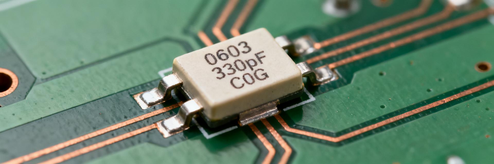
330pF denotes the nominal capacitance; coding like “331” maps to 330 pF using standard EIA value codes. C0G (NP0) is a Class 1 dielectric with near-zero temperature coefficient and minimal aging, chosen for stability over X7R/X5R. 0603 is the imperial footprint (approx. 0.06"×0.03", metric 1608). Common tolerances are ±1% and ±5%, chosen based on circuit budget and cost.
Typical applications where 330pF C0G 0603 is preferred
Engineers pick 330pF C0G 0603 for timing networks, RF matching, oscillator stability, precision filtering, and sensor front-ends. Priorities are low loss, minimal DC-bias shift, and long-term stability—making C0G ideal where frequency stability and low phase-noise impact system performance.
Datasheet essentials: which specs matter and why
Electrical specs to read first (capacitance, tolerance, rated voltage, temp coefficient)
Begin with nominal capacitance, tolerance, and the dielectric temp coefficient. Datasheet test conditions (frequency—often 1 kHz or 1 MHz—AC test voltage, and 25°C reference) determine listed values. Rated DC voltage for 0603 MLCCs ranges commonly from low tens of volts up to several hundred volts; check the specific part’s rated voltage and then consider practical derating for margin.
| Parameter | Typical Spec (C0G/NP0) | Standard Test Conditions | Design Context |
|---|---|---|---|
| Capacitance | 330 pF | 1 MHz ± 10%, 1.0 ± 0.2 Vrms | High-frequency filtering / RF matching |
| Tolerance | ±1% (F) or ±5% (J) | 25°C ambient temperature | ±1% yields precise cutoff in timing paths |
| Temp. Coefficient | 0 ± 30 ppm/°C | -55°C to +125°C (reference 25°C) | Zero thermal drift across operating range |
| Dissipation Factor (DF) | < 0.1% (Q ≥ 1000) | 1 MHz, 1.0 Vrms, 25°C | Ensures low power loss and minimal heat |
Loss-related specs (dissipation factor, ESR, insulation resistance, leakage)
Look for dissipation factor (DF or tan δ) at the datasheet test frequency—C0G should show very low DF, implying high Q and low insertion loss. Insulation resistance and leakage current matter when the capacitor forms part of a high-impedance node. MLCC datasheets usually tabulate DF and leakage under defined conditions; use those numbers to predict loss in your operating band.
Mechanical & environmental specs engineers can't skip
Package, footprint, and dimensional drawing
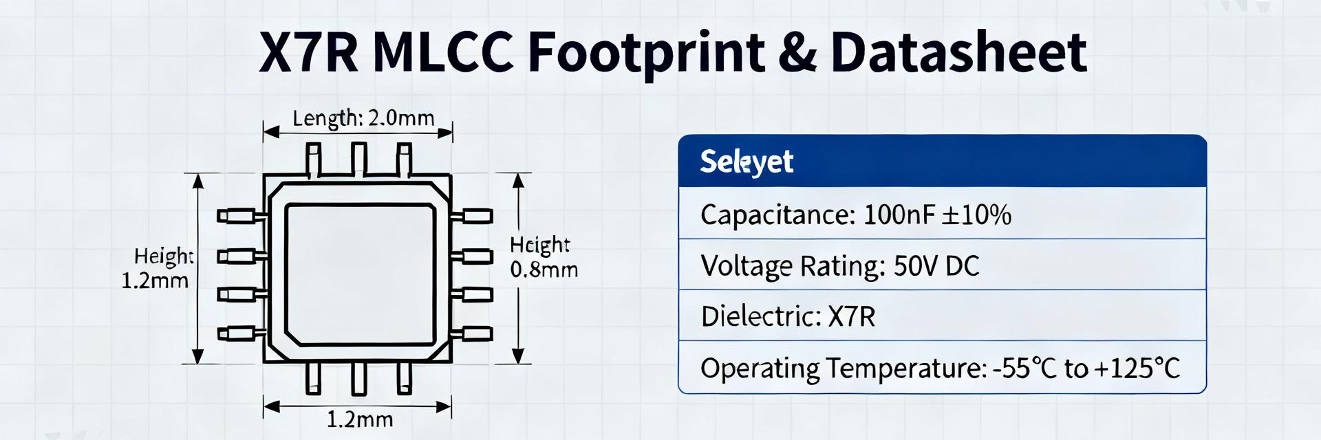
Datasheets include nominal 0603 dimensions, recommended land pattern, and package tolerances; these govern solder fillet quality and risk of tombstoning. Mismatched pad geometry or excessive paste can cause assembly defects—follow the recommended footprint and solder paste stencils to ensure reliable joints.
Temperature range, aging, and reliability ratings
C0G parts typically support wide operating ranges (e.g., well below −40°F to above +257°F equivalent ranges in °C terms) and exhibit minimal ppm/°C drift. Aging for C0G is negligible compared with high‑κ dielectrics. Check MSL, reflow profile limits, and mechanical stress tests on the datasheet for assembly and reliability planning.
Performance metrics & measurement considerations (data deep-dive)
Self-resonant frequency, ESL, and real-world behavior at high frequency
Self-resonant frequency (SRF) marks where capacitive reactance equals inductive reactance; above SRF the part behaves inductively. 0603 package ESL contributes to SRF; datasheet impedance vs. frequency plots show this behavior. If plots are absent, plan bench impedance sweeps to locate SRF and confirm suitability at your operating frequency.
DC bias and temperature effects for C0G
C0G exhibits minimal capacitance change with DC bias compared to high‑κ dielectrics, but conservative designs verify the C vs. V curve on the datasheet. Rule of thumb: always confirm datasheet or measurement data when operating near rated voltage to avoid unexpected capacitance loss in-circuit.
How to translate specs into design choices (methods & examples)
Example — RC filter / timing network design using a 330pF C0G 0603
To design a 10 kHz single‑pole RC low‑pass with C = 330 pF, use fc = 1/(2πRC). Solving R = 1/(2π·10e3·330e‑12) ≈ 48.2 kΩ. A ±1% capacitor tolerance shifts fc by ±1%; using ±1% C0G reduces corner drift compared with ±5% parts. Confirm datasheet test frequency vs. your operating band when mapping listed capacitance to circuit response.
Layout and assembly best practices
Keep capacitor leads and traces short, place decoupling caps close to pins, and stitch ground near RF caps to minimize loop inductance. For 0603, proper pad size and balanced paste deposition reduce tombstoning. Follow the part’s max reflow temperature and recommended profile to preserve termination integrity.
Selection criteria & procurement checklist for engineers
Choosing tolerance, voltage rating, and package variants
Choose ±1% when stability and corner accuracy matter; use ±5% where cost and volume dominate. For voltage, derating rules vary by dielectric—C0G shows less DC bias effect, but allow margin by selecting a rating that keeps operating voltage well below the rated maximum for long life and lower leakage.
What to request from suppliers and what to test on receiving parts
Request datasheet items before purchase: dimensional drawings, test conditions, impedance/SRF plots, and reliability test results. Incoming inspection should include sample C measurement at operating frequency and temperature, IR/leakage checks, visual termination inspection, and X‑ray or solderability tests when warranted.
Short case study: specifying a 330pF C0G 0603 for a precision oscillator
Requirements & target specs
Target: low phase noise and tight frequency stability across −40°C to +85°C. A 330pF C0G 0603 with ±1% tolerance is a candidate because of low DF and minimal temp coefficient. From the datasheet, confirm DF, temp coefficient, SRF, and rated voltage to ensure the part meets oscillator stability needs.
Verification plan and expected measurements
Lab tests: measure capacitance at operating frequency and bias, record oscillator frequency drift vs. temperature, and compare phase-noise with alternate caps. Pass/fail criteria: capacitance shift and DF within datasheet limits under operating conditions; otherwise reject or qualify with additional screening.
Summary
Reading the 330pF C0G 0603 datasheet with attention to test conditions, loss figures, SRF/ESL, rated voltage, and temperature specs converts a nominal part number into a predictable, fit-for-purpose component. Confirm reflow limits, package dimensions, and run a brief verification plan on received parts to validate in-circuit behavior.
- Focus on datasheet test conditions (frequency, temperature) when mapping listed capacitance to circuit behavior for 330pF C0G 0603.
- Low DF and minimal DC bias shift make C0G preferable for timing and RF; verify SRF/ESL for high‑frequency use.
- Choose ±1% tolerance for precision; request impedance plots and reliability data from suppliers before procurement.
Common questions engineers ask about 330pF C0G 0603
How much does DC bias affect a 330pF C0G 0603?
C0G dielectrics show minimal DC-bias induced capacitance loss compared with high‑κ ceramics; however, confirm by checking the part’s C vs. V curve on the datasheet or measuring samples. For conservative designs, validate at the actual operating voltage and temperature.
Which specs on the datasheet predict RF suitability for a 330pF C0G 0603?
Key RF indicators are impedance vs. frequency plots, SRF, and ESL plus DF at the relevant test frequency. Low DF and a high SRF relative to the operating band indicate good RF performance; absent plots, perform bench impedance sweeps to qualify the part.
What procurement checks should include the word “datasheet” for a 330pF C0G 0603?
Require the datasheet to include dimensional drawing, test conditions (frequency, temperature, AC test voltage), impedance/SRF plots, DF, insulation/leakage data, and reliability test results. Verify these items against your application needs before bulk purchase.
What is the difference between C0G and NP0 dielectrics for this capacitor?
C0G and NP0 represent the same class of ultra-stable Class 1 ceramic material. NP0 is the military designation (Negative-Positive-Zero), while C0G is the EIA designator specifying 0 ±30 ppm/°C capacitance drift. They are equivalent and fully interchangeable.