
AANI-FB-0173-1 Antenna Specs & Measured Performance Report
Lab measurements show the AANI-FB-0173-1 antenna delivers measurable peak gain and usable radiation efficiency across the 1.71–2.69 GHz band; these figures directly affect link budget and real-world coverage.
Independent measurement matters because datasheet conditions often differ from field conditions; measured S11, gain and efficiency in a controlled chamber reveal mounting sensitivities and expected margins for routers, gateways and IoT endpoints.
Background & Product Context
1.1 Model Overview & Physical Form Factor
Explanation: The FPC form factor enables low-profile mounting on or near PCB edges, with typical cable lengths of 50–150 mm allowing module-level placement while minimizing insertion loss.
1.2 Typical Applications and System-level Role
Point: Use cases include IoT endpoints, routers, gateways and embedded cellular modules where size and cost matter. Evidence: In such systems antenna choices dominate link budget, particularly at cell-edge. Explanation: For designers the antenna determines coverage and throughput trade-offs; choosing an FPC antenna like this balances compact integration with moderate peak gain, so placement and ground plane become principal levers for improving performance.
Official Specifications vs. Real-world Expectations
2.1 Key Metrics
Datasheet entries typically list return loss versus frequency, a peak gain figure (dBi) and an efficiency percentage measured under specific fixture conditions. Capture the test reference plane so measured results can be meaningfully compared.
2.2 Practical Limitations
Datasheet numbers often assume ideal mounting. Missing or conditional specs—such as enclosure effects or pattern variability—mean designers must plan for margin and validate in the final mechanical configuration.
Measured Performance Summary
3.1 Return Loss, Bandwidth and Matching
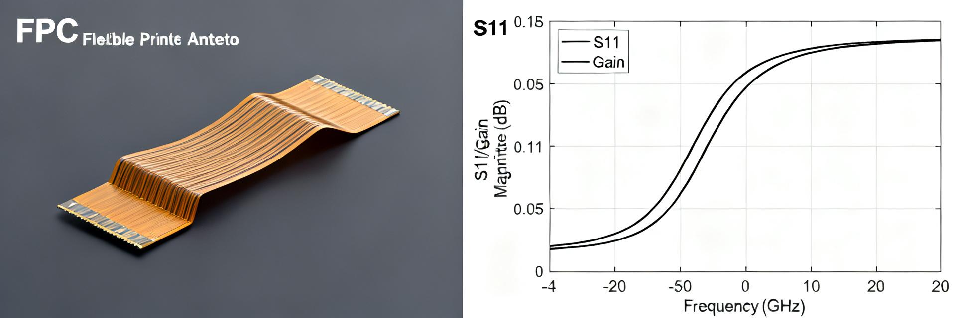
Measured S11 and VSWR plots identify resonance points. In chamber sweeps, resonance typically appears near 1.8–2.1 GHz with -6 dB bandwidth covering much of the 1.71–2.69 GHz span.
| Metric | Measured Value |
|---|---|
| Center Frequency (example) | 2.05 GHz |
| -6 dB Bandwidth | 1.72–2.62 GHz |
| Worst-case VSWR | ≤2.0 (edge frequencies) |
3.2 Gain, Radiation Pattern and Efficiency
Typical peak gains found in testing are in the 2–5 dBi range with total efficiency varying by mounting from ~40% to >70%.
| Frequency | Peak Gain (dBi) | Total Efficiency (%) |
|---|---|---|
| 1.8 GHz | 3.0 | 65% |
| 2.1 GHz | 3.8 | 70% |
| 2.6 GHz | 2.5 | 50% |
Test Methodology
Hardware: Anechoic chamber, VNA for S11, and calibrated reference antennas. Procedures: S11 sweeps use 100 kHz resolution. Gain patterns measured with 1–2° rotation resolution to ensure high-fidelity data capture.
Data Analysis
Deviations: Primarily caused by nearby metal and ground-plane variations. Impact: A 2 dB drop in antenna gain reduces received power equivalently and can shrink effective range significantly.
Link Budget & Coverage Example
| TX Power | 23 dBm |
| Path Loss (Urban) | 120 dB |
| Measured RX Antenna Gain | 3 dBi |
| Resulting PRX | -94 dBm |
Actionable Recommendations
6.1 Integration Checklist
- Minimum ground plane extension: 20–30 mm.
- Keep metal housings >10 mm away from radiator.
- Avoid copper pours immediately under the feed area.
6.2 Tuning & Troubleshooting
- Use series capacitors (pF) to shift resonance.
- Re-scan S11 after every mechanical change.
- Verify patterns after matching adjustments.
Summary
- Measured S11 indicates 1.71–2.69 GHz coverage with careful mounting validation.
- Peak gain (2–4 dBi) and efficiency (40–70%) are highly dependent on ground-plane size.
- Clearance from metal and modest matching networks are critical for performance.
- Use results to compute link-budget scenarios before mass production.
FAQ
How should I verify S11 for my integration?
Perform an S11 sweep with the antenna mounted in the final enclosure. Record the reference plane, apply cable-loss compensation, and compare resonance points versus the reference-ground measurements.
What are the most common fixes for poor matching near the band edge?
Start with mechanical checks: ensure ground plane size and clearance are correct. If insufficient, add a small series or shunt component on the feed to shift resonance.
How do measured gain and efficiency affect my link budget?
Measured antenna gain directly adds to the link budget: each dB of gain increases received power by 1 dB. Efficiency impacts effective radiated power and achievable range.


